
Prolec GE
Single-Phase Pad-Mounted Transformer
Single-Phase Pole-Type Transformer
Secondary Substation Transformer
NEMA 3R Certification PGE SHV
ISO 9001:2015 Certificate
Controlled High Energy Safe-NET® Tank Design Sequence
EHS Policy – Prolec GE Brazil
Flexible Autotransformer
FPE Models TC-525/546 Spring Drive Tear Down, Maintenance & Repair
In this white paper, we will discuss tear down, maintenance and repair of the FPE TC Series spring drive mechanisms. We stock many of the components that will be discussed and for those who might be interested, we offer full tear down and overhaul services for each of the FPE TC Series spring drive mechanisms. As a part of the discussion, a comparison of the models that were produced will be offered and the key differences in the models will be highlighted and described. The information we provide will help to ensure you properly identify your model and are positioned to recognize and procure any replacement components that you ultimately need as a result of your inspection. Key activities that should be completed, including major items that should be inspected and maintained, will be listed and discussed. Helpful tips to aid in tear down and inspection will also be shared.
Two major variations of the FPE TC spring drive mechanisms were manufactured. Much of the design and “componentry” of each variant were similar, but they were not identical. The first variant model numbers are TC-525 and TC23-2. The second variant model numbers are TC-546, TC15 and TC23-1. Referring to the series of figures below (labeled Figure 1), the main differences between the model variants are labeled and described.
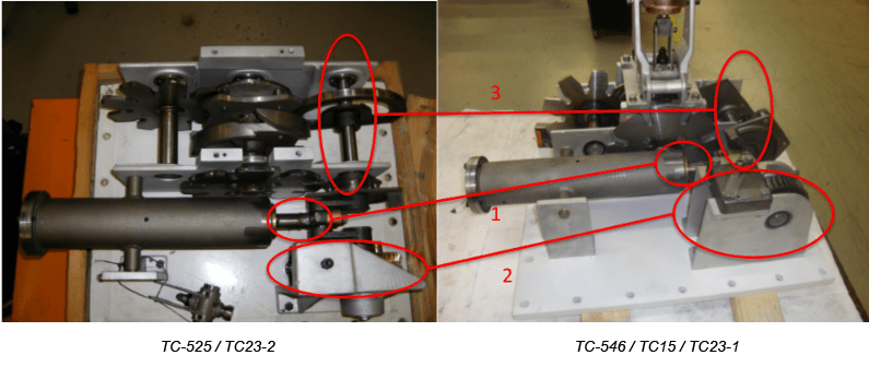
Figure 1 above depicts a top view of each variant in which three main differences in the two models are circled in red and numbered. Below is the description of each of the numbered differences:
- Drive spring barrel assembly for the TC-525 has a 1″ diameter shaft, while the same shaft on the TC-546 has a 3/4″ diameter.
- Dimensions and materials of the vertical drive shaft, worm gear and worm gear support structure are different.
- Dimensions and materials of the lock plate and first shaft assembly are different.
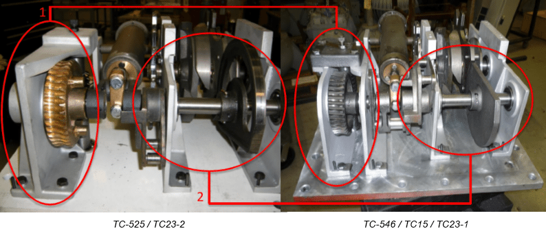
Figure 2 above provides a left side look at both variants, resulting in another view of two of the three main differences in the models. The differences are circled in red and numbered. Below is the description of each of the numbered differences:
- Dimensions and materials of the vertical drive shaft, worm gear and worm gear support structure are different.
- Dimensions and materials of the lock plate and first shaft assembly are different.
INSPECTION AND EVALUATION OF COMPONENT WEAR
The next few figures depict examples of the “typical” wear conditions that can be found during the tear down and inspection of the FPE TC Series spring drive mechanisms. Descriptions of the specific wear conditions are presented in Figures 3 through 7, including visual identifiers which help illustrate the worn condition and aid in pinpointing locations of key components that should be inspected.
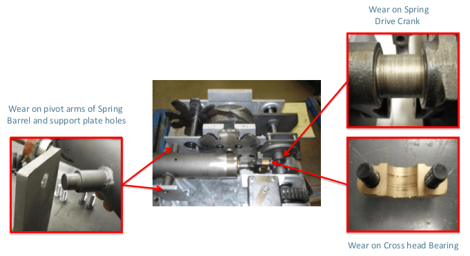
Figure 3 above shows the locations and types of wear that can occur on the spring barrel mount and support plate holes. Typical wear on the spring drive crank and the cross head bearing is also depicted.
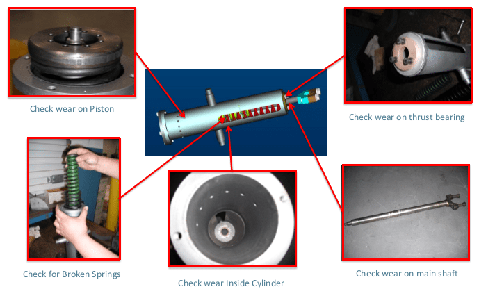
Figure 4 above provides visualizations of each of the major inspection points on the main spring drive barrel assembly. Brief descriptions of the individual items are included for reference.
Figure 5 below shows the locations and types of wear that can occur on the Geneva wheels and scroll cam. Excessive wear and separation of the laminated plates on both Geneva wheels are shown. NOTE: The scroll cam depicted in the picture has excessive wear.
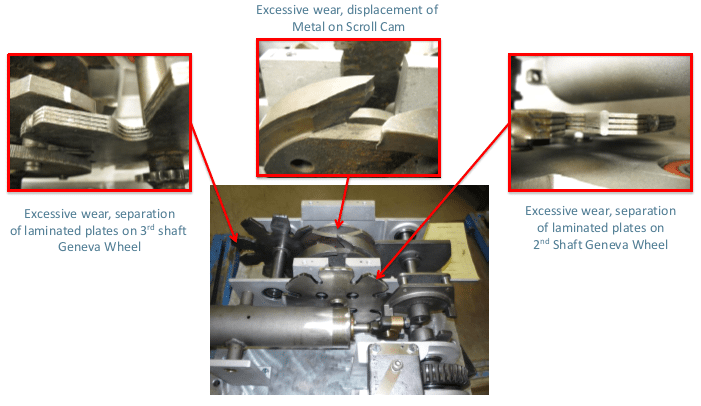
Figure 6 below shows the locations and types of wear that can occur on the vertical shaft. Pay special attention to worn or broken teeth on the worm gears. Also, inspect the area where the shaft seals contact the shaft to ensure that grooves have not worn into the shaft.
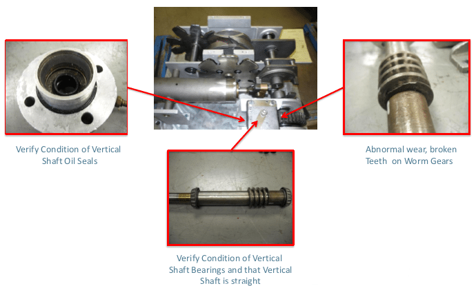
Ensure the vertical shaft is straight and verify condition of the oil seals. Refer to Figure 7 below for detailed information on the two types of vertical shaft oil seal assemblies that were used.
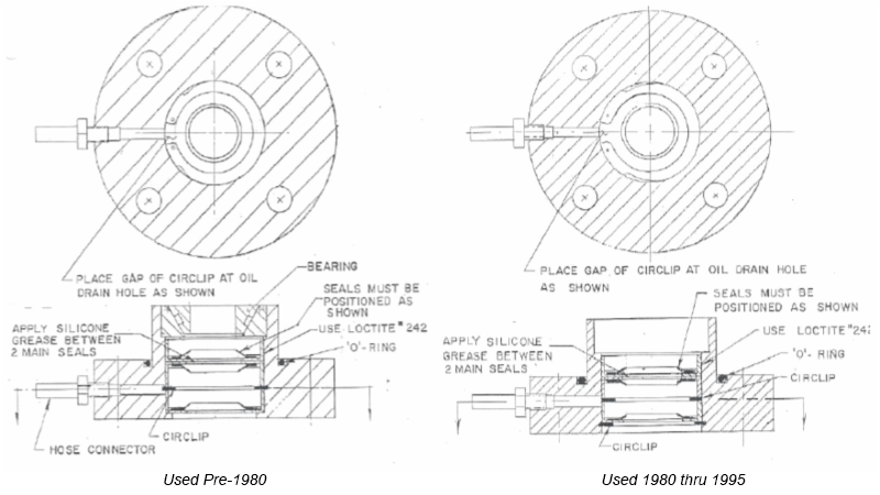
Figure 7 above contains schematics of the two oil seal assembly configurations for the FPE TC Series spring drive mechanisms. When inspecting your FPE TC spring drive mechanism, this is a component that should always be inspected in detail and care should be taken to verify the condition of the oil seal assembly. For the TC-546, the replacement part number is 4000-682. For the TC-525, the replacement part number is 4000-731.
TEAR DOWN, MAINTENANCE AND REPAIR
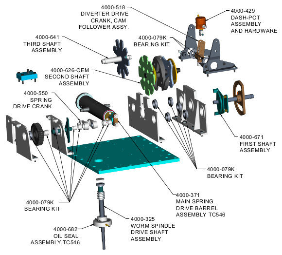
If you plan to self-perform tear down, maintenance and repair of your FPE TC Series spring drive mechanism, several key activities should be completed to ensure high quality results. Those key activities are presented in the bulleted list below for a TC-546 spring drive. The list is accompanied by Figure 8 which includes an exploded view of a TC-546 spring drive mechanism. Figure 8 is meant to provide a visual aid to assist in pinpointing and understanding each of the key activities that need to be performed. Key activities include:
- Always replace all bearings (bearing kit, part number 4000-079K)
- Replace the oil seal assembly
- If the 3rd shaft assembly needs replacement, upgrade to the solid Geneva gear design offered by Waukesha® Components (third shaft assembly, part number 4000-641)
- If the 2nd shaft assembly needs to be replaced, replace with the original Geneva gear design offered by Waukesha® Components (second shaft assembly, part number 4000-626)
- Replace any gears that have broken teeth or exhibit excessive mechanical wear
- Always fully disassemble and fully inspect the main spring drive barrel assembly (main spring drive barrel assembly for TC-546, part number 4000-371)
- Replace all locking hardware, i.e. lock washers, nyloc nuts, locking tabs and spring pins
Finally, when planning to self-perform a comprehensive tear down, maintenance and/or repair of your FPE TC Series spring drive mechanism, always remember to complete the following activities before removing any parts of the assembly:
- Ensure the mechanism is in neutral position
- Match mark all mating gears with metal marker
- Remove all locking spring pins, securing support plates to the mechanism base plate
- Mark current location of all corners of support plates on the base plate for future reference
To learn more about all components available for the Federal Pacific line of LTCs, contact a member of our sales team at 1-800-338-5526. Also, don’t forget about our library of easy-to-navigate, 3D catalogs designed to help you quickly identify and locate hard-to-find components for LTCs and oil circuit breakers. The library also contains several of the Waukesha® Components’ line of Transformer Health Products®.