
Waukesha®
Single Column Breather
Single Column Breather — Español
Single Column Breather Manual
Transformer Life Extension
Performing transformer life extensions (TLEs) is the practice of improving and upgrading an asset, returning it to near new status. TLEs provide a strategic fleet management option to overcome issues with budget, availability, site constraints and/or grid priorities. Current supply chain constraints and longer lead times magnify these issues, making TLEs a viable option for more asset managers.
As defined here, TLEs are done to upgrade and improve critical systems to add useful life to the asset. In contrast, a transformer rewind would be considered a full transformer rebuild. A rebuild is normally considered when a catastrophic event happens in the main tank and the unique nature of the asset requires a like-for-like replacement of the unit. Rebuilt units also serve as a viable alternative on the secondary market.
A TLE is an option when the main tank elements (core and coil) are in excellent shape, and the peripheral elements are contributing to the asset’s limitations. For example, an ideal transformer for a TLE would have DGA and electrical tests on the main transformer tank which indicate a healthy unit, but its arcing-in-oil load tap changer (LTC) is a potential failure point. In this instance, the main tank is healthy and could provide several years of additional service to the utility; however, the LTC’s condition may force a premature retirement of the asset.
Each utility will have its own process for evaluating assets and determining which assets are TLE candidates, but the four main considerations are as follows:
- Unique designs and location constraints
- Health of the candidate units
- Asset classification
- Fleet status and availability of new units
When the design of the existing unit or substation does not allow for a change in footprint, a TLE may be the only option. For these assets, TLEs can help overcome physical constraints. In urban areas where transformers can be located inside structures, replacing a transformer can pose significant challenges.
New designs can change the height, width, or length dimensions, changes that may not conform to existing codes. If the main tank is viable, a TLE will allow the asset to be upgraded in place. Managing the TLE within the existing footprint can eliminate the need for a new substation project.
The health of the main tank is the primary driver when considering a TLE. You should evaluate trend data as well as point-in-time reports to determine the viability of the unit. Both DGA and routine electrical tests should be evaluated. Additional data can also help evaluate the health of the unit, including fault history, PD monitoring data, surge counts, historical load profile, etc. Once the data analysis is complete and the unit is determined to be a candidate, a visual inspection should be performed to determine if any internal issues exist. The decision to perform a TLE is subjective, and each utility will have a threshold for the minimum acceptable condition to move forward.
Two Primary Considerations: Accounting Treatment and Economic Viability
Each utility will have a lower and upper bound for TLEs. The lower bound may be driven by accounting and asset management rules that prescribe the minimum requirements for capitalization of the project. These requirements can be expressed in terms of dollars vs. asset value or in terms of the number of systems addressed. Accounting principles must be considered as well as regulatory requirements and PUC rate case requirements when establishing parameters to evaluate capital reinvestment in an existing unit.
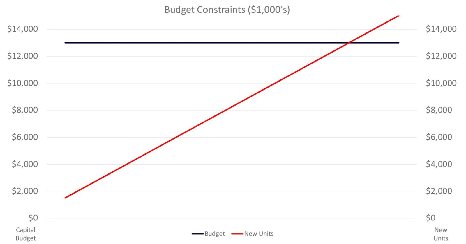
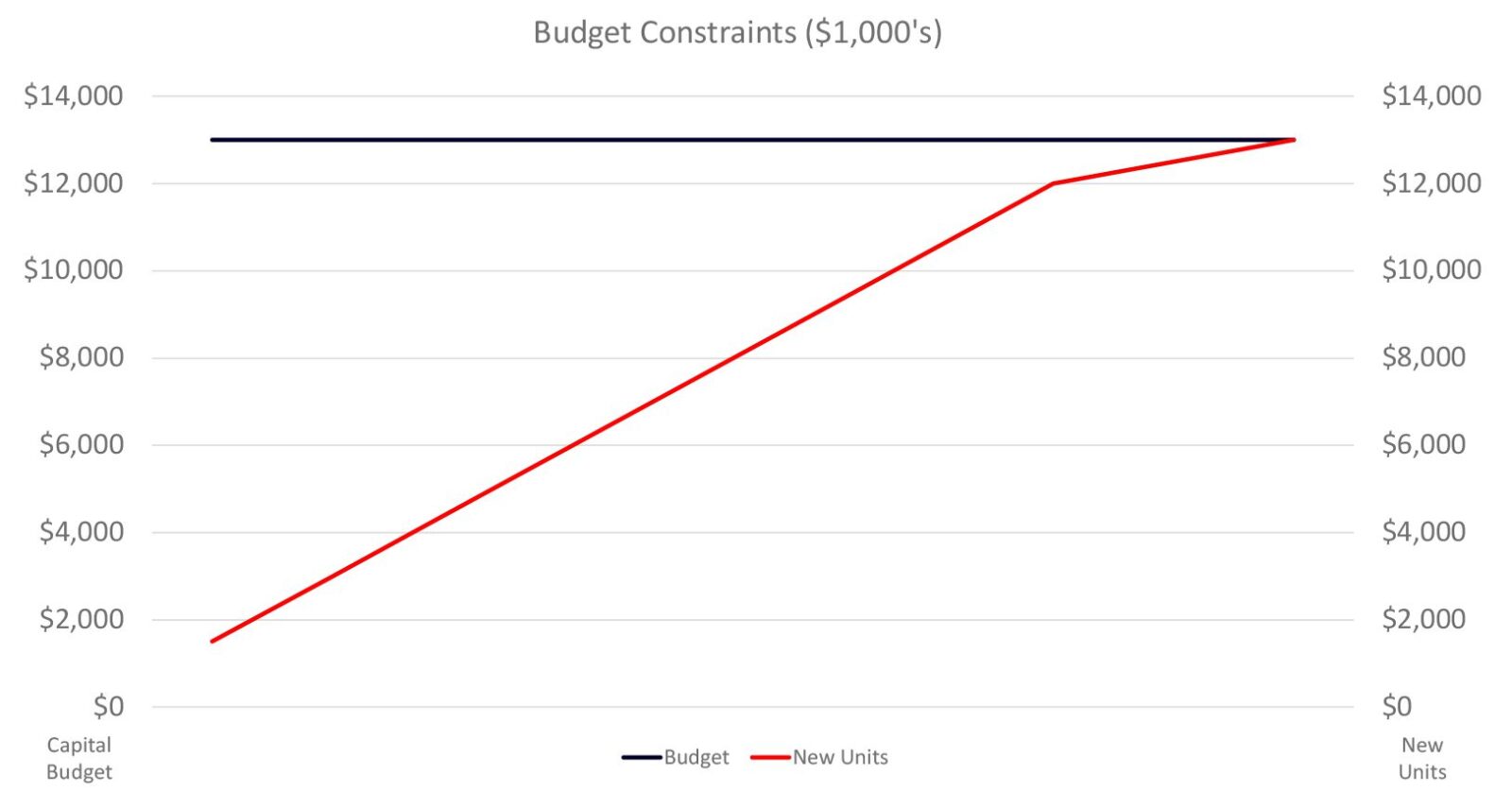
The upper bound is the crossover point where investment in the existing asset no longer makes financial sense. With any capital project, there will be a cost/benefit calculation. Generally, the viability of the TLE diminishes as the value of the upgrades approaches the value of a new asset. Certain assets will not warrant a TLE. The cost of updating an older asset compared to the cost of a new asset and the ability to establish a longer depreciation schedule on the new asset will naturally drive a decision for the new asset.
Situations exist where the status of the utility fleet, spares, and upcoming expansion projects will influence the TLE decision. When the available budget or number of assets becomes finite and the current assets outstrip available resources, extending the life of existing assets can overcome the shortfall. This can be a temporary strategy to minimize the impact of point-in-time conditions, or it can augment a new unit strategy. TLEs allow utilities to manage expansion, non-viable unit replacement, and service levels to customers.
Once assets are evaluated and identified for TLE, scope of work elements are identified. Each utility will have its own process for evaluating the elements to include in a TLE, but here are six considerations:
- Load tap changer: upgrade or retrofit
- Electrical controls: wiring, terminal blocks, gauges, fuses, relays, breakers, and heaters
- Electrical load handling: bushings, arresters, and leads
- Fluid cooling and breathing: radiators, fans, pumps, coolers, conservator, and breathers
- Monitoring and controls systems: alarms, protection, and asset monitoring
- External tank upgrades: painting, crack repair, and leak mitigation
LTC Updates
One of the weakest systems on a transformer is the LTC. The LTC is a common—and often catastrophic—failure point. Arcing-in-oil units require periodic inspection and maintenance to ensure proper operation, and older vacuum systems do not benefit from the design improvements realized over the last 50 years. Moving from either of these systems to newer technology can extend the life of the transformer and minimize ongoing maintenance costs. Retrofitting the LTC with a new vacuum unit is a significant upgrade to the transformer. However, the ability to upgrade to new vacuum technology depends on the design of the transformer. Each unit must be evaluated and inspected to verify the unit qualifies for an LTC retrofit. Once validated, a complete set of engineering drawings is produced to include the new vacuum LTC. The LTC retrofit is a significant project that can take 30+ weeks from identification to commissioning; however, the total transformer outage time to perform the upgrade is typically only two to three weeks, including LTC throat wall retrofits.
Transformers that utilize outdated, maintenance intensive vacuum tap changers also benefit from upgrades that take place during transformer life extensions. First generation vacuum systems may require more frequent maintenance or adjustment to perform properly. Current generation LTCs improved the reliability of the systems, but older units may require upgrade or replacement to overcome limitations of the earlier designs.
Controls Upgrades
Electrical controls within the transformer are frequently upgraded during the life extension process. Gauges that monitor performance of the unit’s temperature, pressure, tap position, and fluid level are replaced with modern equivalents that have outputs for external monitoring. Control cabinets on field-aged transformers normally have multiple modifications performed by field crews that sometimes render the original control drawings inaccurate. The life extension process involves a reengineering effort that can include replacement of control cabinet wiring as well as components within the control cabinet of an outdated design that are no longer produced, such as fuses and terminals.
Heaters in the control cabinet along with relays and breakers used for auxiliary power handling are frequent sources of unplanned maintenance for field personnel during inspections on aged assets. The TLE investment offers replacement of these 20 to 50-year-old electrical items. Replacing the auxiliary control devices also provides the opportunity to decrease auxiliary voltage from 480V to 240V to accommodate modern safety practices that require arc flash protective equipment for 480V environments.
Electrical Load Handling
Bushings can also be upgraded as part of the TLE process. Due to their flammability, oil-impregnated paper (OIP) bushings can cause significant damage to other components, the main transformer, and even other systems in the substation. Upgrades to resin-impregnated paper (RIP) bushings can provide lower partial discharge, zero headspace, better physical characteristics, and are non-flammable while also offering lower external current leakage and reduced risk of flashover in contaminated coastal environments. Utility design parameters and preferences will influence adoption of this technology; however, a retrofit with RIP bushings can provide an upgrade to the transformer.
External arresters used for lightning and over voltage protection are normally replaced during the TLE upgrades. Aged porcelain-insulated arresters are frequently upgraded to new polymer sheathed designs that offer better performance in industrial and coastal environments. System conditions normally evolve during a transformer’s life cycle, which could provide an opportunity to optimize the arrester’s maximum continuous operating voltage, fault magnitude, and energy ratings for current requirements. Lower temperature operation along with replacement of the bolted electrical connections will reduce arrester maintenance and call-out visits in the future.
Improved Cooling Performance
Upgrades to the cooling system offer multiple benefits to the life of the transformer. Both fans and pumps are rotating assemblies and performance can degrade or fail over time. Upgrading to new fluid handling equipment will help restore the cooling capabilities originally designed into the transformer. In addition to ensuring all components are working, upgrading to modern, higher CFM, lower amp draw, sealed bearing fans—or even adding fans to the system—will help maintain operating temperatures in the main tank. Pump performance is also critical to maintaining the appropriate cooling.
Radiators used in transformer construction evolved from tube-based designs to more efficient plate-based coolers. Radiator performance increases from header pipe design, cooler efficiency, and cleanliness might add years to the life of a field-aged transformer. Modern radiators are more durable with longer lifespans, and most are zinc-coated to further extend life. Radiators will be replaced as part of a scheduled TLE.
Replacement of the conservator bladder, the Buchholz relay, and sudden pressure relay will restore the transformer’s oil handling and fluid-based protection systems. Leaks in the rubber conservator bladder increase moisture contamination within the transformer’s main tank and cause premature degradation of
in-tank insulation. Breathers are often upgraded to self-drying models to reduce O&M costs associated with replacing desiccant. If the transformer is nitrogen blanketed rather than a conservator design, replacement of the cylinder regulator and cylinder itself will be evaluated along with the potential addition of a nitrogen generator system.
Monitoring
The addition of real-time monitoring equipment as part of a TLE upgrade provides the transformer owner the opportunity to reduce maintenance visits. Gas-in-oil monitoring, partial discharge, remote temperature outputs, and bushing monitoring are useful additions to consider when performing a proactive life extension. Trending data that can be accessed remotely helps identify issues early before a critical failure occurs.
External Considerations
Aged transformers frequently suffer from fluid leaks and external tank degradation, such as rusting and welding cracks. The re-gasketing of fluid handling equipment on the transformer during a TLE might also include an external inspection that results in a recommendation to paint the outside of the transformer’s main tank. In salt air contaminated environments, paint deterioration is a frequent maintenance item that can be greatly improved with a deep cleaning and full “top to bottom” recoating. Failed welds and joints can be repaired on-site to decrease future maintenance visits and third-party contractor expenditures.
With a proactive and calculated approach to TLEs, a utility can improve the overall quality of its fleet. TLEs can provide reductions in forced outages, unit failures and maintenance. They can also improve quality of service, maximize spend, and allow for greater flexibility when dealing with spares and expansion. Transformer life extensions are another tool to ensure the reliability of the grid and high service levels while adding years to the life of the assets.
After the life extension, you could have:
- Solid main tank (tested and inspected prior to project)
- Modern load tap changer (a weak link in transformers with arcing-in-oil or early vacuum LTCs)
- New controls and information devices
- Improved electrical load handling (potentially safer and more reliable than existing equipment)
- Better cooling performance
- Upgrades to real time monitoring, and
- Refreshed externals
Waukesha® UZD® Annual Inspection Form
Waukesha® UZD® LTC Upgrades and Enhancements
Since its introduction, the Waukesha® UZD® has developed a track record as a trusted and reliable high speed resistance bridging load tap changer (LTC). Today there are more than 6,500 units in service. Over the years, several design modifications have been introduced that have enhanced operation and improved reliability of the Waukesha® UZD® LTC. This Tech Tip will highlight the most significant design upgrades and enhancements that have been made over the years. Detailed information on the purpose and impact of each will be illuminated. We will also provide access to other key technical resources that you can use to better understand the operation and maintenance needs of your Waukesha® UZD® LTC.
The UZD is a three-phase, fully insulated, externally mounted load tap changer designed to be applied to liquid-filled power transformers. It is a 33-position switch designed for plus/minus operation by use of a reversing change-over selector switch. The UZD is rated to carry a maximum through current of 600 amps at a nominal system operating voltage of 34.5 kV.
The main tank of the UZD LTC is comprised of two compartments. The first is an oil-filled switching compartment with a 100 gallon oil capacity. This oil-filled compartment houses the tap selector and the reversing change-over selector switch. The second compartment of the main tank is air-filled and is home to the spring drive mechanism. The spring drive mechanism is connected via driveshaft to the motor drive mechanism which is located in a separate ancillary enclosure called a BUE. The BUE provides mechanical power to the spring drive mechanism and houses electrical control, signaling and protection equipment.
In the following sections, the modifications that will be addressed have been grouped together in subsections based upon their physical location. The subsections represented below are the switching compartment, spring drive compartment and BUE motor drive enclosure. This grouping aids in pinpointing the physical location of each modification and can be utilized for top level planning of inspection and maintenance activities.
SWITCHING COMPARTMENT
The vast majority of modifications developed over the years are applicable to components that are located in the switching compartment. Figure 2 below is a graphic depiction of one of the three identical cast epoxy phase moldings with assembled contacts located in the switching compartment. Each of the sub-assemblies in which modifications have been developed are identified below by call out arrows with labeled item numbers.
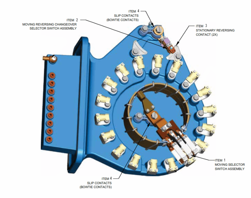
Item 1 in Figure 2 above is the moving selector switch assembly. Figure 3 below shows a detailed view of the moving selector switch assembly and an individual view of a contact roller sub-assembly.
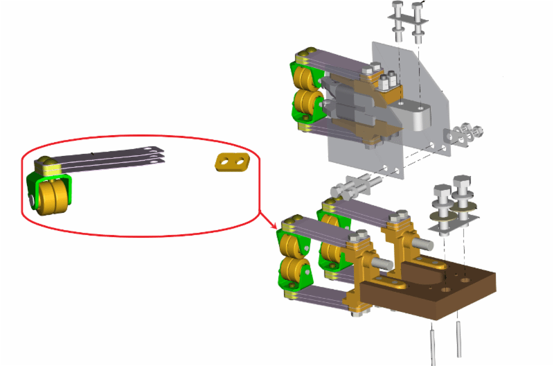
Our first example of components that have been modified are circled in red above. In order to increase contact pressures, the leaf spring count of each of the sub-assemblies was increased from two to three. Additionally, the design of the pins that secure the rollers was changed from hollow to solid to increase rigidity and reliability. An edge radius was also added to the rollers to reduce wear and a nib was added to the collar to improve alignment in the sub-assembly. These modifications are offered as part of a kit under part number 1030-027K-OEM.
Figure 4 below is an enlarged view of the area of the phase molding that includes the complete reversing change-over selector switch assembly.
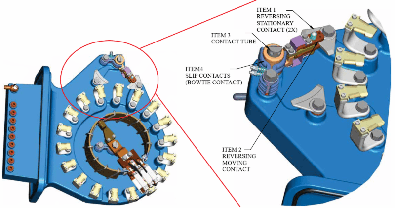
Figure 5 below is an exploded view of Items 1 and 2 depicted in Figure 4 above. Item 1 is the reversing stationary contact which has seen two modifications to enhance performance. First, the mounting hole was offset to improve alignment between the moving and fixed contact. This change was made in 1991. In 1994, the finish of the contact surface was changed to a 32 micro-inch polish. If your unit is older, you might want to consider changing the reversing stationary contact to the new style which includes both enhancements. The associated part number is 1030-384P.
Item 2 is the reversing moving contact sub-assembly. In 1997, several design changes were incorporated into this sub-assembly to improve performance. The number of contact points and the spring pressures were increased. The springs were moved outside of the current path. A self-aligning feature was built into the main current path and a backup shunt was added. Item 2 is available under part number 1030-371P.
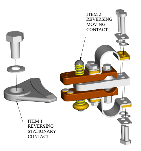
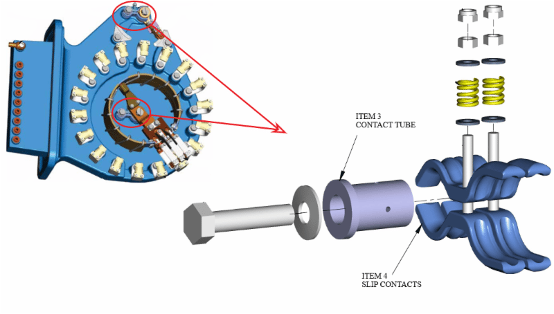
Figure 6 below is an exploded view of the main slip contact sub-assembly. This sub-assembly is applied in both the selector and reversing switches. The location of the slip contact sub-assemblies in the fully assembled phase molding are indicated by the circled areas in the figure on the left. The contact tube labeled below as Item 3 has been improved by changing to a machined copper material with thicker tube wall and an integrated shoulder. The original design utilized a steel washer. The changes improved reliability of the sub-assembly and reduced the operating current density. The applicable part number for the improved contact tube is 1030-065P. Item 4 below depicts the slip contacts. In 1992, the design was modified to increase contact surface area. The revised design is available under part number 1030-025K.
Rounding out the upgrades available for the switching compartment are those that were initially introduced to enhance unit reliability by improving oil quality. In 1988, the original flat door gasket, part number 2011486, was replaced with an “O” ring gasket to achieve better sealing and longer service life. The “O” ring gasket is carried under part number 2007012. For units produced before mid-year 1995, there is a universal entrance tube kit available. This kit allows the customer to add a UZD oil filter without having to drill holes and weld joints in the field. The part number for this kit is 1030-014K. Finally, the 2nd generation auto-recharging dehydrating breather (ARDB2) is recommended. When properly installed, the ARDB2, part number ARDB2-0000, keeps the LTC oil dry and does not require maintenance personnel to periodically change-out the silica gel.
SPRING DRIVE COMPARTMENT
The spring drive compartment is situated adjacent to the selector compartment and is not oil filled. The spring drive allows the tap changer to be operated manually while energized and carrying load. Once charged and activated the stored energy in the spring drive mechanism results in high speed operation and minimum arcing time. The design of the spring drive mechanism ensures that each tap change is consistent and unaffected by voltage interruptions or manual hand cranking speed. Figure 7 below depicts the fully assembled spring drive mechanism as it is mounted in the spring drive compartment.
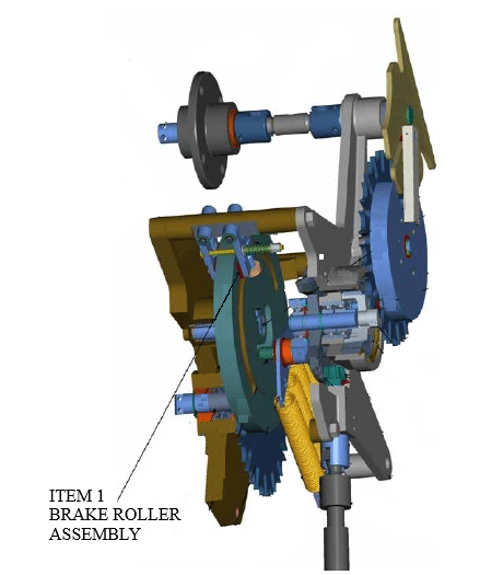
Figure 7: Spring Drive Mechanism
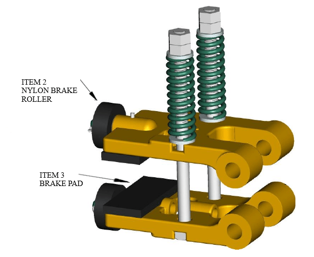
A magnified view of Item 1 in Figure 7 at right is presented in Figure 8 below. There have been two enhancements made to the brake roller assembly of the UZD. The first is listed as Item 2 below. The nylon brake roller was changed from the original nylon material which was white in color to a new nylon material that is black in color. A lubricated bronze insert was also added to the new black nylon roller to improve wear characteristics. The brake rollers can be purchased individually under part number 1030-043K or they also come installed as part of the full assembly as depicted in Figure 8 below, available under part number 1030-042K. Item 3 in Figure 8 are the brake pads. Originally, the brake pads were secured to the shoes via rivets. In the new design, the pads are glued to the shoe to improve resistance to corrosion in the connected area.
BUE MOTOR DRIVE ENCLOSURE
The BUE motor drive enclosure shown in Figure 9 below includes the drive motor that charges the spring battery in the spring drive compartment which operates the LTC. The BUE motor drive enclosure is located at a convenient height and includes the operation counter and position indicator for the LTC. The BUE motor drive enclosure is readily accessible at ground level for inspections and maintenance.
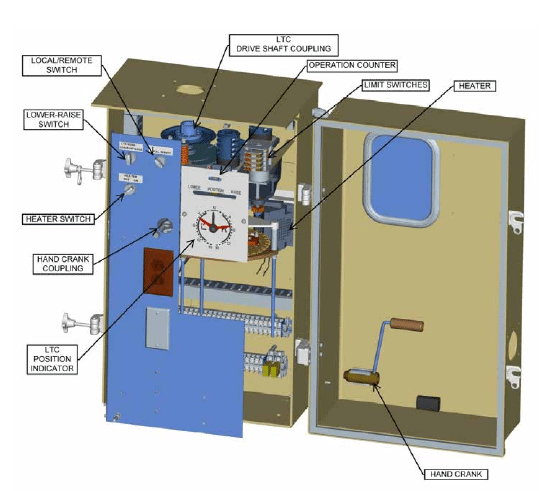
Figure 10 below is a graphic of the a BUE motor drive without the enclosure. There have been three notable enhancements made to the BUE motor drive. The location of each of the enhancements has been indicated in Figure 10 below.
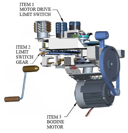
The motor drive limit switch labeled as Item 1 above was changed in 2010. Of note is the fact that the old and new switches are not interchangeable. Item 2 above is the limit switch gear. In 2005, the gear material was changed from nylon to brass. This change was made to improve reliability of the gear assembly. The gear and associated accessories are available as a kit under part number 1030-1741K.
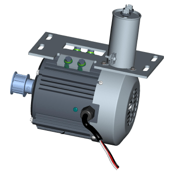
The most significant change made to the BUE is the drive motor itself. The original ASEA drive motor was changed to a Bodine motor in 1991. At the time this change was made, the motor mount assembly was modified to accommodate the taller American Solenoid limit switches. These switches are blue in color. The drive motor and associated mounting hardware as shown in Figure 11 below are offered as a kit under part number 1030-031K.
As the OEM for the UZD load tap changer, we have developed several resources designed to assist our customers in understanding, operating and maintaining the UZD. Specifically, we offer the following UZD resources for download from our website:
• UZD 3D Catalog
• UZD Maintenance Manual
• UZD Technical Manual
• UZD Brochure
We welcome calls from customers seeking technical support on the UZD. If you need assistance, we will gladly work with you to support your needs on the UZD.
To learn more about all components available from the Waukesha® Components, contact a member of our sales team at 1-800-338-5526. Also, don’t forget about our library of easy-to-navigate, 3D catalogs designed to help you quickly identify and locate hard-to-find components for LTCs and oil circuit breakers. While a link is included above to the UZD catalog, the library also contains catalogs for most other major legacy LTCs and several of the Waukesha® Components’ line of Transformer Health Products®.